1 Das UCD-Format (Unstructured Cell Data) ist ein allgemeines Datenformat für Finite Elemente Gitter das in den Visulaierungsprogrammen der Firma AVS (Advanced Visual Systems) verwendet wird. Die folgende Formatbeschreibung in englischer Sprache wurde einer AVS-Dokumentation entnommen. Von den im AVS-UCD-Format unterstützten Elementtypen (cell-type) werden in Rismo2D die ein- und zweidimensionale Elemente (line, tri und quad) unterstützt.
A) Description of Format
Unstructured Cell Data (UCD) is commonly used in structural analysis and computational fluid dynamics. A UCD data structure consists of an irregular coordinate structure (or "model") made up of cells. Cells may be points, lines, quadrilaterals, triangles, tetrahedrons, pyramids, prisms, or hexahedrons. Each cell has a corresponding number of nodes. Data can be associated with the entire structure, with each cell, and with each node. The data is structured as a set of components. each component can be either a scalar or a vector.
If a UCD file is in ASCII, it has the following format. For a more com-plete description of UCD file formats, as well as a discussion of UCD data in general, see the "Unstructured Cell Data" appendix of the AVS Developer's Guide.
Comments, if present, must precede all data in the file - comments within the data will cause read errors. The general order of the data is:
1. Numbers defining the overall structure, including the number of nodes, the number of cells, and the length of the vector of data associated with the nodes, cells, and the model.
2. For each node, its node-id and the coordinates of that node in space. Node-ids must be integers, but any number including non-sequential numbers can be used. Mid-edge nodes are treated like any other node.
3. For each cell: its cell-id, material, type (hex, prism, pyr, tet, quad, tri, line, pt), and the list of node-ids that correspond to each of the cell's verticies. (The UCD appendix shows the order in which cell verticies are numbered.)
4. For the data vector associated with nodes, how many components that vector is divided into (e.g., a vector of 5 floating point numbers may be treated as 3 components: a scalar, a vector of 3, and another scalar, which would be specified as 3 1 3 1).
5. For each node data component, a component label/unit label pair, sepa-rated by a comma.
6. For each node, the vector of data values associated with it.
That is the end of the node definitions. Cell-based data descriptions, if present, then follow in the same order and format as items 4, 5, and 6.
The single model-based data descriptions, if present, comes last.
The input file cannot contain blank lines or lines with leading blanks. The numbers down the left correspond to the above descriptions and are not part of the ASCII file.
The UCD structure and library will support either integer or character node-, cell-, and model-ids, (referred to in the library documentation as names). However, the read ucd module only accepts integer node-ids, cell-ids, and model-ids. This is shown in the example below. The ids do not have to be consecutively numbered.
Also note that, at present, most of the UCD modules do not make use of cell and model-based data, thus the input data examples all show "0" for and . User-written modules can use the UCD library to manipulate cell- and model-based data.
| # <comment_1> . . . # <comment n> |
|
| 1. |
<num_nodes> <num_cells> <num_ndata> <num_cdata> <num_mdata> |
| 2. |
<node_id 1> <x> <y> <z> |
| 3. | <cell_id 1> <mat_id> <cell_type> <cell_vert 1> ... <cell_vert n> <cell_id 2> <mat_id> <cell_type> <cell_vert 1> ... <cell_vert n> . . <cell_id num_cells> <mat_id> <cell_type> <cell_vert 1> ... <cell_vert n> Note: valid strings for <cell-type> are: pt, line, tri, quad, tet, pyr, prism, and hex. |
| 4. | <num_comp for node data> <size comp 1> <size comp 2> ... <size comp n> |
| 5. | <node_comp_label 1> , <units_label 1> <node_comp_label 2> , <units_label 2> . . <node_comp_label num_comp> , <units_label num_comp> |
| 6. | <node_id 1> <node_data 1> ... <node_data num_ndata> <node_id 2> <node_data 1> ... <node_data num_ndata> . . <node_id num_nodes> node_data 1> ... <node_data num_ndata> |
| 7. | <num_comp for cell's data> <size comp 1> <size comp 2> ... <size comp n> |
| 8. | <cell-component-label 1> , <units-label 1> <cell-component-label 2> , <units-label 2> . . <cell-component-label n> , <units-label n> |
| 9. |
<cell-id 1> <cell-data 1> ... <cell-data num_cdata> |
| 10. | <num_comp for model's data> <size comp 1> <size comp 2> ... <size comp n> |
| 11. | <model-component-label 1> , <units-label 1> <model-component-label 2> , <units-label 2> . . <model-component-label n> , <units-label n> |
| 12. | <model-id> <model-data 1> ... <model-data num_mdata> |
The UCD data structure has eight different cell types. In figure each of the cell types is pictured, with its nodes and mid-edge nodes correctly labeled.
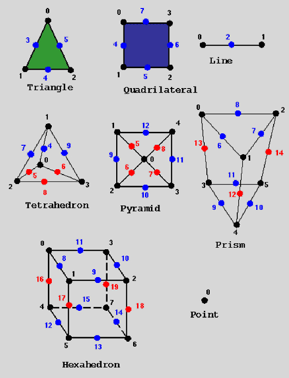
Figure UCD Cell Types, Nodes, Mid-Edge Nodes. and Node Numbering
The following is an example of a simple UCD file. This UCD structure has 8 nodes in 1 hexahedral cell. Associated with each node is a single scalar data value, making up one component that this person labels "stress," and specifies a "lb/in**2" unit label. There is no cell- or model-based data. See the "Unstructured Cell Data" appendix in the Developer's Guide for more examples.
| 8 1 1 0 0 | 1. 8 nodes, 1 cell, 1 component of node data |
| 1 0.000 0.000 1.000 2 1.000 0.000 1.000 3 1.000 1.000 1.000 4 0.000 1.000 1.000 5 0.000 0.000 0.000 6 1.000 0.000 0.000 7 1.000 1.000 0.000 8 0.000 1.000 0.000 |
2. for each node, its id and node coordinates |
| 1 1 hex 1 2 3 4 5 6 7 8 | 3. cell id, material id, cell type, cell vertices |
| 1 1 | 4. num data components, size of each component |
| stress, lb/in**2 | 5. component label, units label |
| 1 4999.9999 2 18749.9999 3 37500.0000 4 56250.0000 5 74999.9999 6 93750.0001 7 107500.0003 8 5000.0001 |
6. data vector for each node |
|
|
|
letzte Änderung:
|